
Modelica Series V - Wastewater Overflow
- Written by: Erik Åberg
Welcome to the fifth chapter of our Modelica Series. In this tutorial, we'll use the Fluid library of the Modelica Standard Library to investigate and find solutions to a pressing real-world problem, Wastewater overflow.
If you've missed the previous chapters of this series, it might be a good idea to read them through before starting with this one. You can find the first chapter here.
Combined Sewer Overflow
In the previous chapters of this series, we've learned to create and simulate system models based on the Modelica language. In this chapter, we'll apply some of our newfound modeling skills to a real-world problem, overflow in combined sewer systems. It is a serious issue that causes water pollution and overfertilization in streams, lakes, and seas. Now more than ever, the problem needs our attention. Sewer overflows are likely to become more common in the future due to urbanization and climate change.
Let's start by getting acquainted with the system at hand.
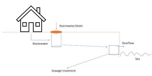
In our example, we'll study overflow in a combined sewer system. Such a system uses combined piping to transport stormwater and sewage water to a sewage treatment plant. Overflow happens when the water flow through the system exceeds the capacity of the piping or the treatment plant.
Fluid modeling in Modelica
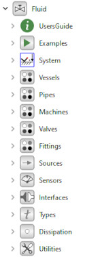
To model this, we'll make use of components from the Modelica.Fluid library, a sub-library of the Modelica Standard Library.
The library contains a large number of components for modeling and simulation of one-dimensional thermo-fluid flows, such as Tanks, pipes, pumps, and valves.
The components are highly flexible to support a large variety of assumptions and media properties. Predefined media properties are available in a separate sub-library of the Modelica Standard Library, called Modelica.Media.
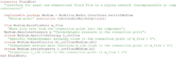
The connectors used in the library are called FluidPorts. They use pressure, p, as the potential variable and mass flow rate, m_flow, as the flow variable. In addition, the connector interface contains some special variables marked with the Modelica keyword stream. These variables are used to describe quantities carried by the flow, such as enthalpy and mass fractions of substances.
It seems we should be able to find all components we need in the Modelica.Fluid library. Let's get to the modeling!
Sewer system without overflow
So, if sewage overflow is so bad, why was this capability added to sewer systems in the first place? We'll try to answer this in our first experiment by implementing a sewer system without overflow capability.
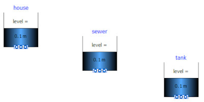
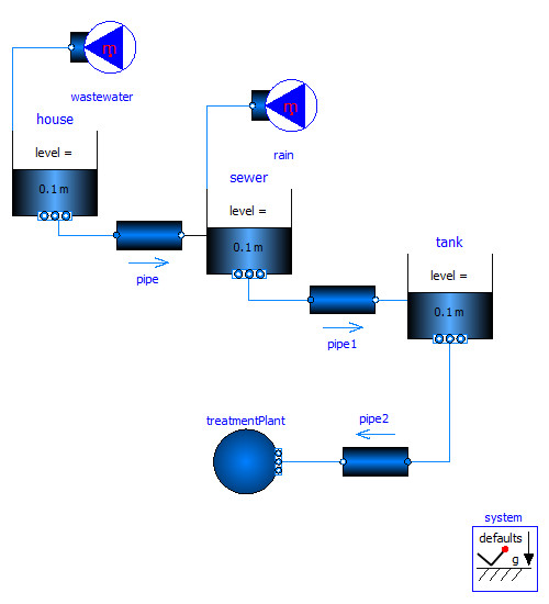
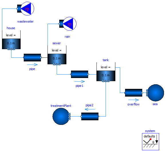
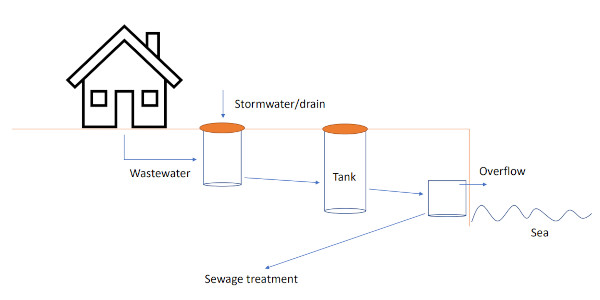
Start by creating a new model in your Modelica editor and call it WaterOverflow. Go to the Diagram view of the Editor and drag and drop three open tanks (Modelica.Fluid.Vessels.OpenTank) to the model. Name them "house", "sewer", and "tank". The "house" tank represents a house that produces wastewater. The "sewer" tank is a combined sewer where the wastewater from the house gets mixed with stormwater. The "tank" tank represents the splitting point that controls the overflow. As mentioned earlier, we won't model the overflow in our first experiment. But let's add the tank anyway. We might need it in later experiments.
Now, drag and drop three static pipes (Modelica.Fluid.Pipes.StaticPipe) and a Modelica.Fluid.Sources.FixedBoundary to the model. Name the boundary component treatmentPlant. Connect one of the pipes in between the house and the sewer. Connect the second pipe to the sewer and the tank. Then, connect the last pipe in between the tank and the treatment plant.

We now need to add some flow sources to our model. Drag and drop two mass flow sources (Modelica.Fluid.Sources.MassFlowSource_T) to the model and name them wastewater and rain. Connect the wastewater source to the house and the rain source to the sewer. We're almost done now. We just need to add one last component to finalize the system model: Modelica.Fluid.System. It is a system component that defines common system properties, such as gravity and initialization. Go ahead and add the component. When you are ready, you should have something like this:
Medium and system parameters
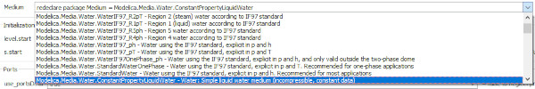
Before we can simulate the model, we need to change a few parameters. The first, and maybe the most important, parameter to change is what media properties to use. We need to change this in all components except in the System component. Open the parameter dialog of each component and select Modelica.Media.Water.ConstantPropertyLiquidWater as the Medium. Note that, in some Modelica tools, it is possible to make a bulk change by selecting all components before opening the parameter dialog.
We also need to change the values of the parameters listed below:
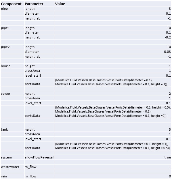
The portsData parameter in the house, the sewer, and the tank define the diameter and the height of the different tank ports. This data, as presented above, assumes that you have connected the tank components in the order described earlier in this tutorial.
Now, let's simulate!
Simulating the system
Simulate the system for 700 seconds and plot the variables house.level, sewer.level, and tank.level. What do you see? Is it the behavior you expected?
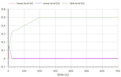
It should be! The system we've modeled in this experiment shows operation during a sunny day. The house produces wastewater at a constant pace, but thanks to the sunny weather, no stormwater is produced. The water flow stays within the capacity of the sewer system. You can see this in the plots. The tanks reach their steady-state levels without overflowing.
Now we know that our system works as expected during a sunny day. Let's see what happens if we add some rain. Open the parameter dialog of the rain source and change its mass flow rate parameter to 10 kg/s, (rain.m_flow = 10). Then, simulate 700 seconds and plot the levels of the different tanks.
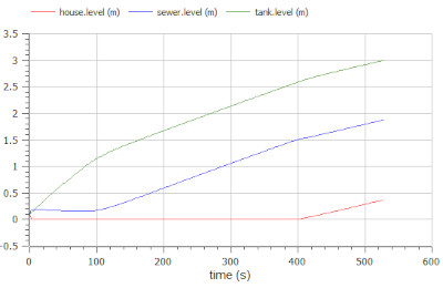
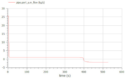
Something has changed! The water flow through the system now exceeds the capacity of the treatment plant and the piping. The water has nowhere to go and starts to fill the tank. Eventually, the tank gets full, and the simulation terminates. The water even flows back towards the sewer and into the house. You can see the backflow in the system by plotting the mass flow rate in the pipe between the house and the sewer: pipe.port_a.m_flow.
Imagine the despair of the house owner. No matter how lovely it is to take a swim, you don't want to do it in your living room! Overflow capability in sewer systems is a way to avoid these situations. Let's see what happens if we add this capability to our system.
Sewer system with overflow
To add the overflow capability, we just need to make some small modifications to the system model. Drag and drop a static pipe (Modelica.Fluid.Pipes.StaticPipe) and a Modelica.Fluid.Sources.FixedBoundary to the model. Name the pipe "overflow" and the boundary "sea". Change the media used to Modelica.Media.Water.ConstantPropertyLiquidWater in both components. Then, connect the "overflow" pipe in-between "tank" and "sea".
Now, modify the following parameters:
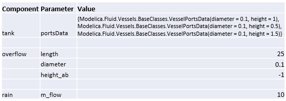
As you can see from the new portsData array, an overflow port has been added to the tank at height=1.5 meters. When the water level reaches this height, it will start to flow towards the sea.
Simulate the system for 700 seconds and plot the tank levels (house.level, sewer.level, and tank.level) and the mass flow rate through the overflow pipe (overflow.port_a.m_flow).
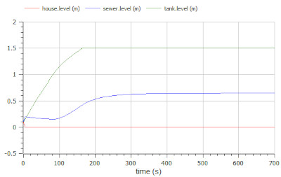
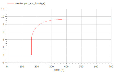
The water flow still exceeds the capacity of the sewer system. However, this time the water can continue flowing downstream thanks to the overflow pipe that we added to the tank. It seems we have solved the backflow issue. But at what cost? With this solution, the wastewater eventually ends up in streams, rivers, and seas...
Using simulation to find a solution
So, how can we reduce the need for overflow in sewer systems? If we managed to reduce the amount of water in the system, overflow wouldn't happen as often. In our model, we can control this by changing the rain.m_flow parameter. Unfortunately, controlling the amount of rain is much harder in the real world. What we can do, is to split the system into two separate systems. One for wastewater. And one for stormwater. This is the way most sewer systems are constructed these days. However, there are lots of older systems out there, and it is not always possible to upgrade to a newer structure. Another way to ease the problem is to make sure that there are enough green areas in cities. These areas help absorb rainwater and reduce the load on the sewer system. We can use simulation as a tool to investigate these different scenarios.
Simulation can also be used for dimensioning and optimization. Both when designing new systems and when improving existing ones. Take a look at this system:
Here, we've introduced another tank that will help us slow the dynamics of the sewer system. This short delay might be enough to avoid sewer overflow in case of heavy rainfall. Feel free to try it out and play around with the model to see if you can find a way to avoid the overflow. In the previous examples, we've used a constant value for the mass flow rates of wastewater and stormwater. To model a heavy rainfall, you might want to use a sine signal as input to the mass flow rate. Open the parameter dialog of the rain source and tick the box, use_m_flow_in, to enable the m_flow_in input connector. You can find the sine source in Modelica.Blocks.Sources. Let us know if you come up with a clever solution to the problem.
As we've seen in this tutorial, Modelica can help us design and optimize sewer systems to avoid wastewater overflow. But, it doesn't stop there. Once we've developed the models in Modelica, we can use them in other contexts. We can export them from Modelica in different formats and share them with colleagues working in other environments. We can even use them as Digital twins together with real-time sensor data to gain deeper insights and predict challenges that are coming up.
We've now learned how to use the Modelica.Fluid library to model a pressing real-world problem. In the coming chapters of our Modelica series, we'll talk more about Modelica, how it works, interfaces, and applications. Stay tuned!
🚀 Ready to Go Further with Modelica?
Take your modeling skills to the next level with our Modelica Introduction Course. In just two days, you'll gain hands-on experience in system modeling and simulation, perfect for engineers, innovators, and anyone ready to build smarter systems.
👉 Explore the Modelica Introduction Course »