Modelica Series III - Connectors and Types
- Written by: Erik Åberg
Welcome to the third chapter of our Modelica Series. In this chapter, we'll take a closer look at connector interfaces and types in Modelica. We'll also dive into the Electrical library of the Modelica Standard Library and use it to model a burglar alarm.
If you've missed the first two chapters of this series, it might be a good idea to read them through before starting with this one. You can find the first chapter here.
Connectors in Modelica
In the previous chapter, we learned how to write equations and wrote our very first Modelica model. A model of a high-flying ball that taught us the dynamics behind the perfect tennis serve. But the model had its flaws. Even though it only described basic physics, like the relation between position, velocity, and acceleration, it was limited to just one application. What if you wanted to apply an external force to the ball? Or use the same model in some other context?
To do that, you would need to add an external interface to the model that defines its boundaries. We call these interfaces connectors since we use them to connect components. There are several types of connectors in Modelica. We use causal connectors when defining input and output signals of components. But most often, we use acausal (non-causal) connectors. A connection between two acausal connectors represents an actual physical connection, such as an electric line or a mechanical coupling.
Confusing? Let's have a look at an example!
Modeling of a Variable Resistor
In this example, we'll model a resistor with variable resistance given by an external input signal. The model should have a connector interface so that it can be connected to other components when modeling electrical circuits. We'll start our modeling effort by adding these connectors.
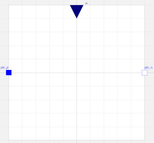
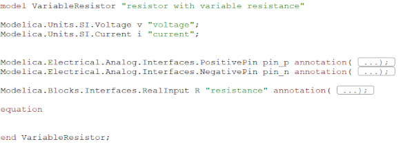
Create a new model in your Modelica editor and call it VariableResistor. Then, go to the Diagram view of your model. Drag and drop a Modelica.Electrical.Analog.Interfaces.PositivePin and a Modelica.Electrical.Analog.Interfaces.NegativePin to the model so that it looks like in the figure below.
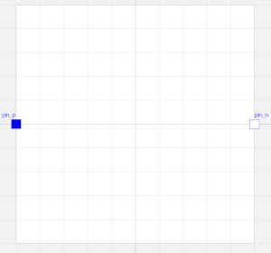
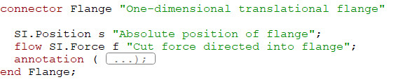
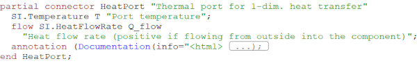
These Pins are the connectors used for most of the models in the Modelica.Electrical library. If you open any of them in the Text view of your Modelica editor, you'll see that they consist of two variables, one for the electrical potential and one for the current.
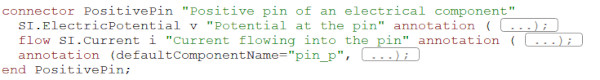
The variable for the current is market with the prefix flow, indicating that it is a flow variable. The variable without the prefix is called a potential variable. When connecting this connector to other connectors of the same kind, your tool will automatically generate some equations. These equations are shown below:
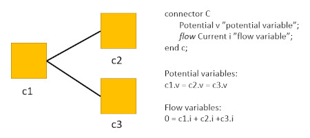
This setup isn't unique for the electrical pin but is typical for all acausal connectors in Modelica. They always consist of at least one potential/flow-variable pair. Here are some examples from the Modelica Standard Library:
In our VariableResistor model, we also need to add a connector for the variable resistance. Drag and drop a Modelica.Blocks.Interfaces.RealInput connector to your model and call it R. This connector is causal and defines an input signal.
Working with units in Modelica
Before we can start adding equations to our model, we need to declare the variables we need. Ohm's law gives us the relation for a resistor:
![]()
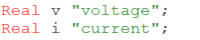
where V is the voltage, R the resistance, and I the current. We've already added an input signal for the resistance, so we just need to add variables for the voltage and the current.
In the previous chapter, we learned about the four default variable types in Modelica: Real, Integer, Boolean, and String, and decided to use Reals for the variable declarations in our High-flying ball model. Making the same choice in the VariableResistor model would give us:
In Modelica, we have the option to add additional attributes to a type. We've already used this feature once in the previous chapter when assigning a start value to the height, h(start=1.2). We can also use this feature for adding a unit, displayUnit, quantity, etc., to the Real type. Adding a unit would make it possible for the Modelica tool to issue a warning or error when we've mixed variables with incompatible units in our equations. If we add units to the VariableResistor model, we get:

However, adding units in this way would be way too time-consuming and lead to mistakes. To solve this, the Modelica Standard Library comes with an extensive number of pre-defined Units that we can use in our models. You can find them in the Units package of the Modelica Standard Library. If we declare the variables of our VariableResistor model using these pre-defined units, we get:
Now, we're ready to add the equations.
Writing the equations
The first thing we need to do is to implement Ohm's law using the variables that we've declared previously. Next, we need to add equations for the relations between the variables of our model and the pin connectors. The voltage of the resistor is the difference in electrical potential between the two pins. The sum of the pin currents should be zero. When done, you should have something similar to:
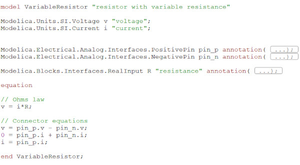
Note that a variable inside a connector can be accessed by "."-notation, i.e., pin_p.v, pin_p.i. Don't forget to use the check functionality of your tool to check the model syntax before moving on to the next step.
Adding an Icon
Before we can use the component in a system model, we need to give it a nice-looking icon. Go to the icon view of your Modelica tool and bring out your inner Michelangelo.
Done! Now that we have a VariableResistor, we can use it for modeling electrical circuits.
The Burglar Alarm
In this example, we'll model a simple burglar alarm. Our variable resistor will represent a Cadmium-sulfide photoresistor (CdS) in this circuit. The resistance over the photoresistor depends on the light intensity. Its resistance is very high in dark environments and low when light hits the resistor. We can use this feature to turn on/off a light-emitting diode (LED).
The LED is on when the room is dark, indicating that no one is around. But then the burglars come! As they open the door and the light hits the resistor, the LED is switched off, indicating that someone is in the room.
Using components from Modelica.Electrical
Modeling electrical systems in Modelica is easy, thanks to the Modelica.Electrical library. It is a sub-library of the Modelica Standard Library that contains a large variety of electrical component models.
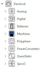
The library contains electrical components for basic analog systems as well as for Digital Electronics, Electrical Machines, Batteries, Polyphase, and QuasiStatic systems.
Let's see if we can use components from this library when modeling the burglar alarm.
Start by creating a new model in your Modelica editor. Call it BurglarAlarm. Drag and drop the following components to the Diagram view of the model: the VariableResistor, Modelica.Electrical.Analog.Sources.ConstantVoltage, Modelica.Electrical.Analog.Semiconductors.Diode, Modelica.Electrical.Analog.Semiconductors.NPN, Modelica.Electrical.Analog.Basic.Resistor, and Modelica.Blocks.Sources.Step. Connect them like in the figure below:
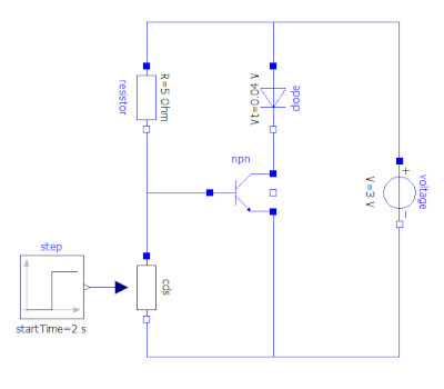
Change the voltage of the voltage source to 3 V and the resistance of the resistor to 5 Ohm. The diode used here is not a LED but is sufficient to show the principles of this burglar alarm. By adjusting the diode voltage drop, you can get it to correspond to LEDs of different colors. Use the step signal parameters below to model that the door of the room opens after 2 seconds.
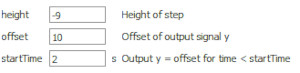
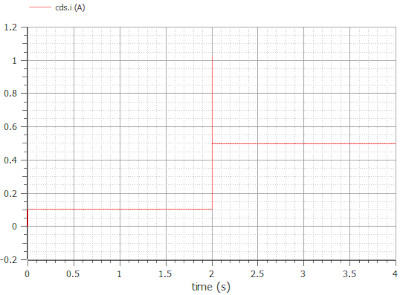
Simulate for 4 seconds and plot the current through the diode and the variable resistor. When the room is dark, the current goes through the diode due to the high resistance of the variable resistor. When the door opens after 2 seconds, this changes. The resistance of the variable resistor is now low, making it the preferred path for the current. Now that you know the principles of this system, you can play around with it, change its parameters, and extend it until you have the perfect alarm system.
We've now learned how to work with connector interfaces, types, and components from the Modelica.Electrical library. In the coming chapters of our Modelica series, we'll talk more about Modelica, how it works, interfaces, and applications. Check out the next chapter now!
🚀 Ready to Go Further with Modelica?
Take your modeling skills to the next level with our Modelica Introduction Course. In just two days, you'll gain hands-on experience in system modeling and simulation, perfect for engineers, innovators, and anyone ready to build smarter systems.
👉 Explore the Modelica Introduction Course »